Have a Question?
How to Install pfSense® CE as a VM on Proxmox VE
Overview
pfSense® CE can be installed and utilized on Proxmox VE as a virtual machine (VM). pfSense® CE is an open source routing and firewall software which is based on FreeBSD. This guide will cover the installation process as well as some additional configuration settings to get pfSense® CE running smoothly on Proxmox VE.
Note: pfSense® CE is open source software developed for the benefit of the community. If you are using pfSense® CE with the Vault, please consider supporting the pfSense project. https://www.pfsense.org/get-involved
Performance Limitations
Although a pfSense® CE virtual machine can be successfully installed on the FW2B, FW4B, and FW4C the performance will be lower when compared to running the VM on our other products. If you wish to use pfSense® CE on an FW2B, FW4B, or FW4C it is recommended to install the operating system as a bare metal firewall rather than running it as a virtual machine on Proxmox VE.
Throughput tests can be found at the end of this article under the "Observed Throughput Speeds" section.
Downloading pfSense® CE ISO
First, head to https://www.pfsense.org/download/ to download the ISO image of pfSense® CE. The latest version of pfSense® CE we have tested on Proxmox VE is 2.7.0.
After the ISO has been downloaded, you will need to upload the ISO to Proxmox VE in order to install the VM.
Uploading the ISO to Proxmox VE
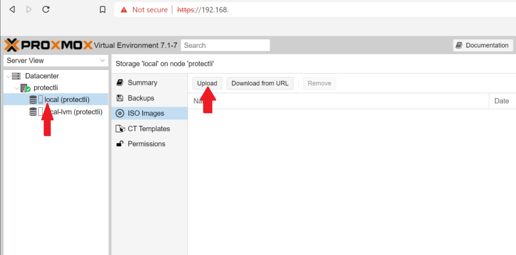
- Login to your Proxmox VE dashboard via your web browser
- On the left side of the dashboard, expand the Datacenter drop-down, and the node with your server name.
- Select your local storage, select ISO Images, and click Upload
- Click Select File and choose your pfSense® CE ISO. Click Upload.
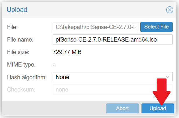
- Verify that the output messages state that the ISO has been imported successfully ("TASK OK")
- Verify that the ISO is viewable on the ISO Images tab on your local storage
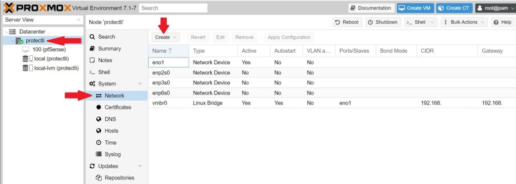
Before we create the VM, we need to create a Linux Bridge on Proxmox VE so we can assign network interfaces on pfSense® CE.
Creating Linux Bridges To Use As Network Interfaces
A Linux bridge is used to bridge your VMs to a physical network device. This allows you to plug in an ethernet cable to one of your Vault's network ports which allows for traffic to travel to/from the VM. Additionally, bridges allow other VMs to acquire an IP through the pfSense® CE VM.
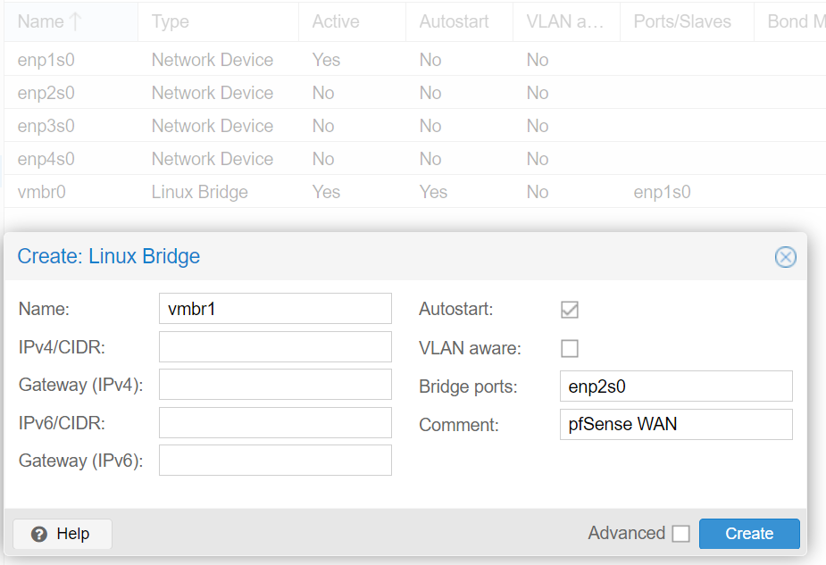
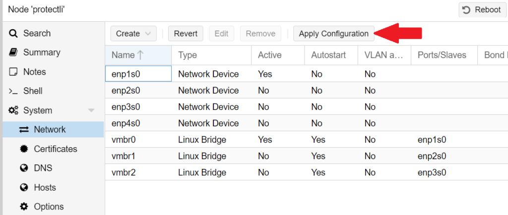
Here at Protectli, we use the default Linux Bridge vmbr0 as the Proxmox VE management port (which is how you are able to access the Proxmox VE web interface). We will create a Linux Bridge for a WAN port (vmbr1) as well as a LAN port (vmbr2). (If you absolutely want to make port 1 pfSense®'s WAN port (vmbr0), you can, but you won't be able to use PCI Passthrough to passthrough the NIC as a PCI device, and there is a chance that performance will suffer. This is because it would be sharing an interface with Proxmox VE's Management Interface)
*Note: If your Vault is capable of PCI passthrough (VT-d), you can assign the network ports directly instead of creating a Linux Bridge. System compatibility and information can be found here. Setup instructions can be found on the "PCI Passthrough for NICs" section on the current page.
- On the Proxmox VE dashboard, select the node with your server's name and choose System > Network
- Click 'Create > Linux Bridge
- In this example, we have Proxmox VE installed on a 4-port VP2420, so we will be using enp2s0 (port 2) for the WAN.
Now that the ISO has been uploaded and you have your interfaces, you can create the VM.
Creating the VM
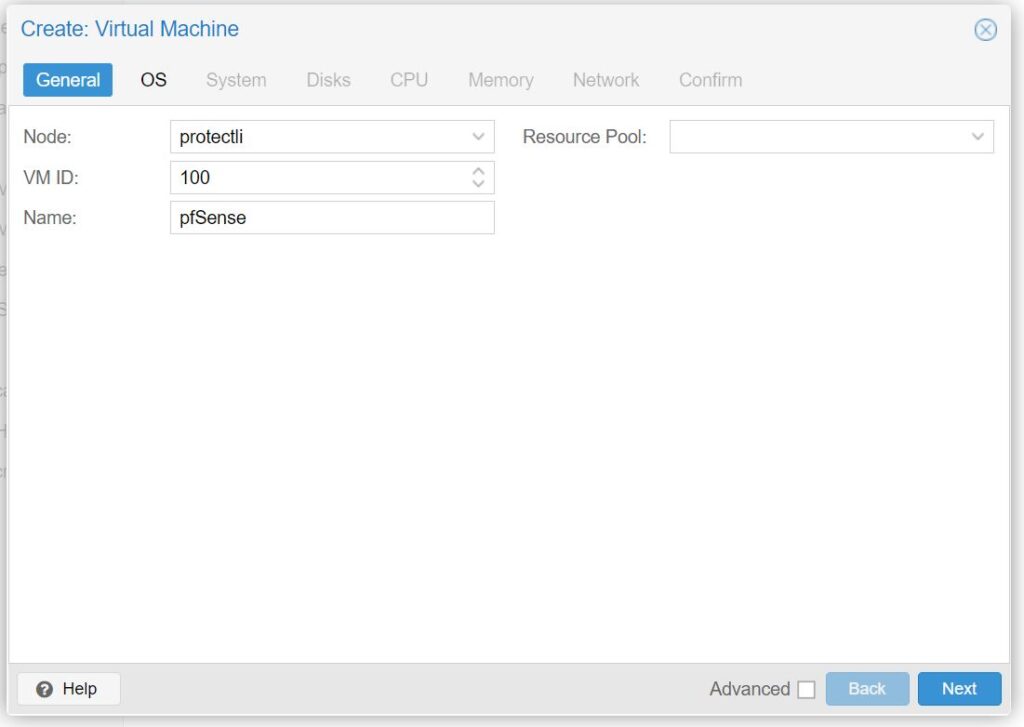
- At the top of the Proxmox VE dashboard, click the blue Create VM button:

- Under the General tab:
- Choose a VM ID number and enter a name for the VM.
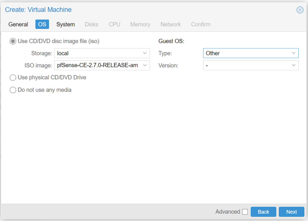
- Continue to the OS tab:
- Choose Use CD/DVD disc image file:
- For Storage: leave the default value of local
- For ISO image: select the pfSense® CE ISO you uploaded earlier
- For Guest OS Type: select Other
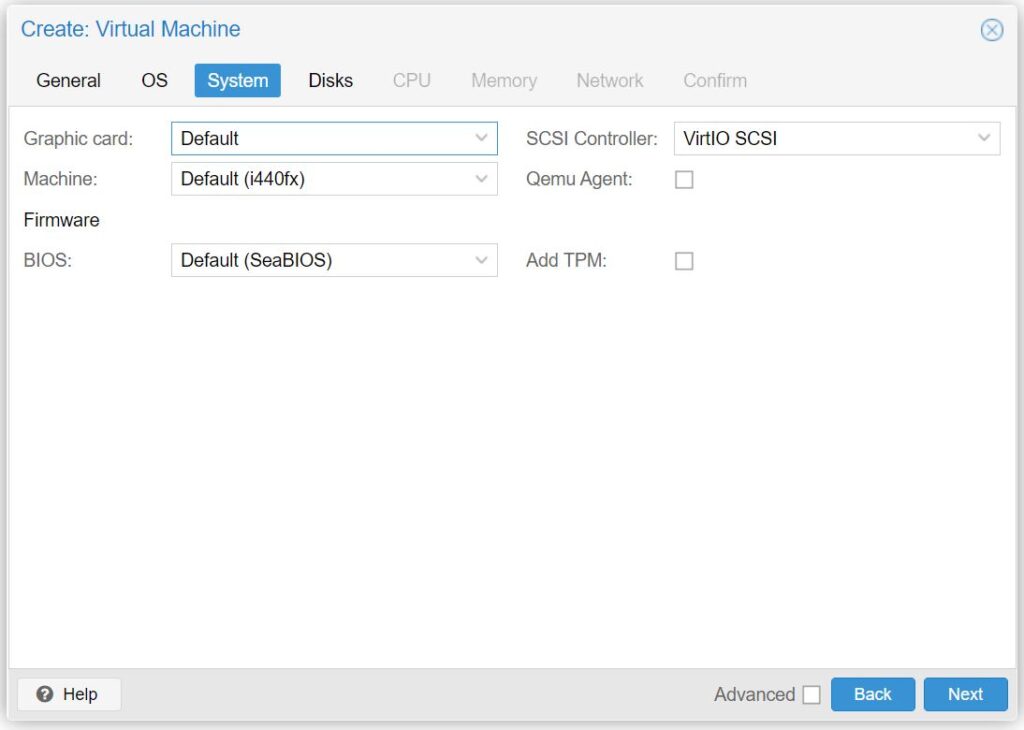
- Continue to System tab:
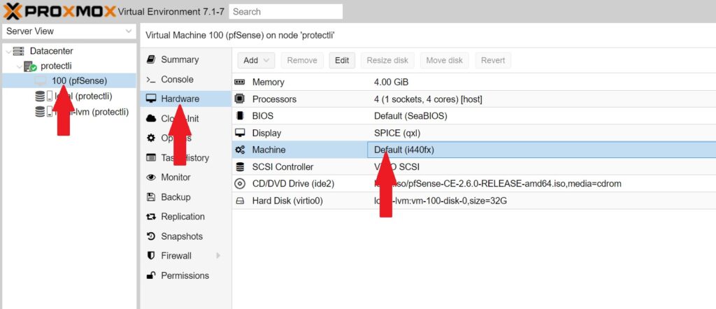
- For Graphic card: select Default
- For Machine: select i440fx
- If you plan on utilizing PCI Passthrough, select q35
- For SCSI Controller: select VirtIO SCSI
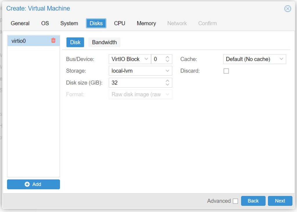
- Continue to Disks tab:
- For Bus/Device: select VirtIO Block
- For Disk size(GiB): choose at least 8GB. In this example we select 32GB.
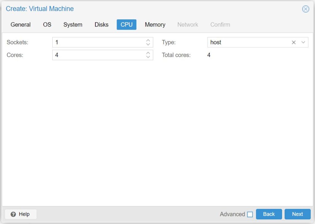
- Continue to CPU tab:
- For Sockets: select 1
- For Cores: select at least 1
- We selected 4 cores for this example, as this is how many cores the VP2420's processor has
- For Type: select host (this will offer some of the best performance)
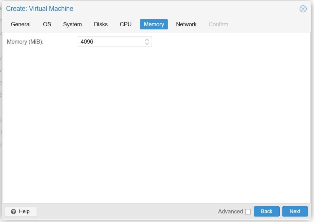
- Continue to the Memory tab:
- For Memory (MiB): select at least 1024
- We selected 4096 (4GB) for this example, this is the minimum recommended amount for performance reasons
- For Memory (MiB): select at least 1024
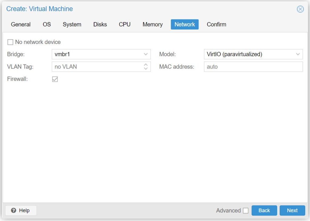
- Continue to the Network tab:
- For Bridge: select vmbr1 (your WAN Linux Bridge)
- For Model: select VirtIO (paravirtualized)
- Continue to the Confirm tab:
- Click Finish
The VM has been created, but we need to add the Linux Bridge for your LAN.
Adding the LAN Linux Bridge to pfSense® CE VM
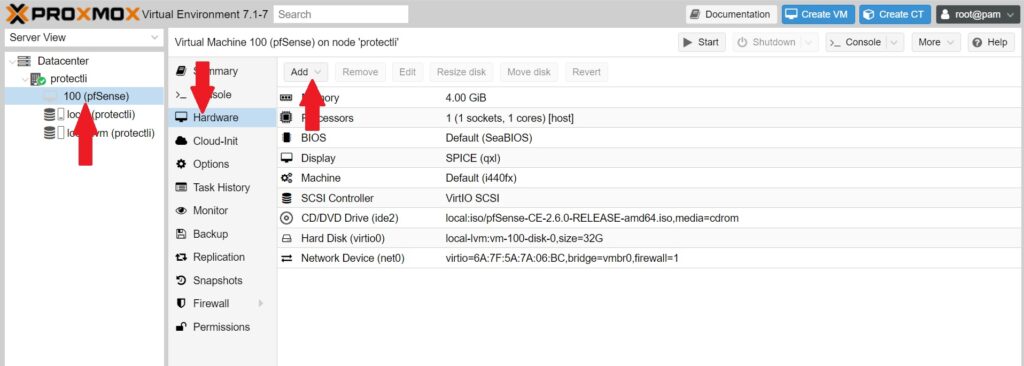
- Choose your pfSense® CE VM located under the node with your server's name
- Select Hardware
- Click the Add button and select Network Device
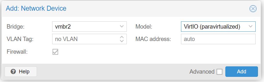
- For Bridge: select vmbr2
- For Model: select VirtIO (paravirtualized)
You now have both a WAN and LAN port to use with pfSense® CE. In this example, it would be ethernet ports 2 and 3 on the Vault.
Starting, Installing, and Configuring pfSense® CE VM
You can now start the VM for the first time, and begin the installation process.
- Click the Start button
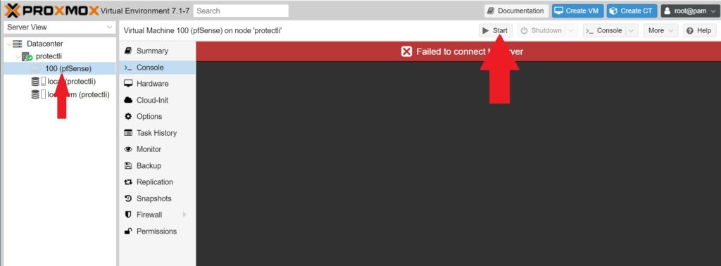
- Choose the Console tab to view the video output
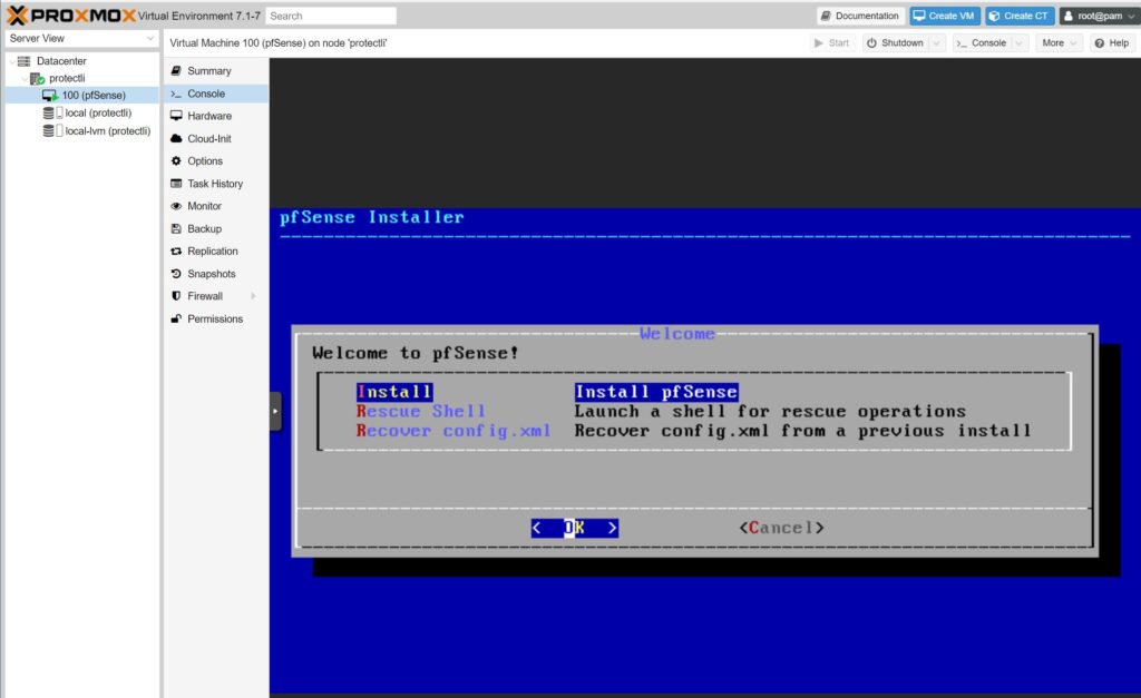
- Let pfSense® CE run until it gets to the Copyright and Trademark Notices
- Accept the notice by pressing Enter on your keyboard
- Press Enter while highlighted over Install pfSense®
- Choose your keymap selection (default should be fine in most cases)
- Choose Auto (ZFS) for your partitioning selection and press Enter
- Press Enter again to proceed with installation
- Select stripe for ZFS Configuration and hit Enter
- Press your Spacebar key to select vtbd0 (there will be an asterisks next to the drive name), and hit Enter
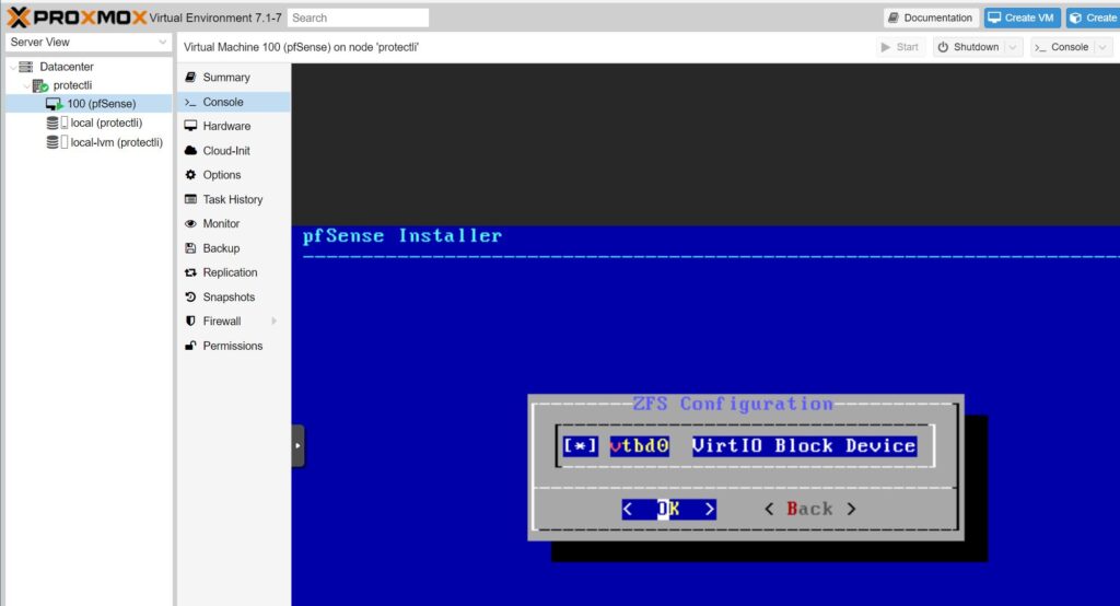
- Select Yes with your arrow keys and hit Enter to confirm the installation location
- Allow installation to finish
- Choose No when asked if you would like to open a shell
- Select Reboot
Configuring interface assignments
After pfSense® CE has rebooted, you will be prompted to setup some initial configuration.
- When asked if VLANs should be setup:
- Type n and press Enter
- For WAN interface, type vtnet0 and hit Enter
- For LAN interface, type vtnet1 and hit Enter
- When asked to proceed, type y and hit Enter
pfSense® CE has now been installed and network interfaces have been assigned (WAN and LAN). You will need to access the pfSense® Web GUI to disable hardware checksums in order for traffic to efficiently pass through the VM. In this example, you can connect a computer to the third port on the Vault to access the webGUI. Alternatively, if you have another VM running on Proxmox (like Ubuntu), and if you have set that VM's network interface as vmbr2, you can access the webGUI through the web browser on the Ubuntu VM.
Accessing Web GUI
We will now disable hardware checksums on the Web GUI. This is an important step!
- Connect a computer to the LAN port of your Vault
- Open a web browser and navigate to the default pfSense Web GUI address of 192.168.1.1
- Login with default credentials. (username: admin , password: pfsense)
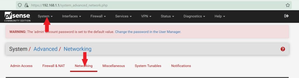
- Go to the System tab at the top and select Advanced
- Select the Networking tab
- Scroll to the Network Interfaces section, and check the Disable hardware checksum offload
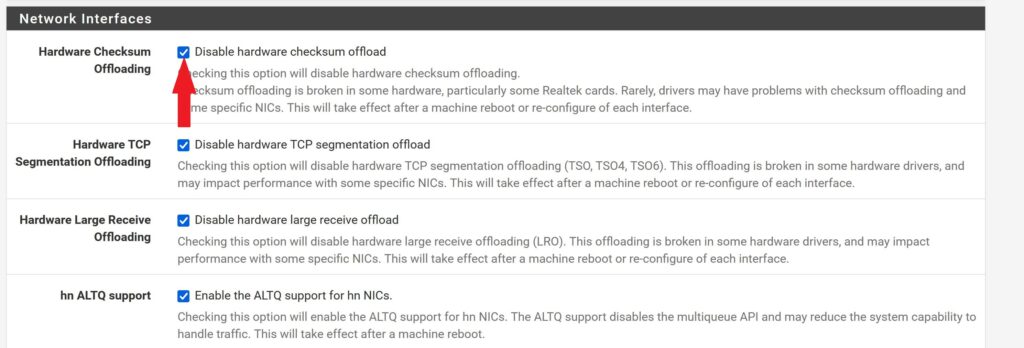
- Hit Save at the bottom of the page.
- Reboot the VM
Congratulations! You now have a working VM of pfSense® CE.
For more detailed configuration instructions, visit the documentation page at: https://docs.netgate.com/pfsense/en/latest/index.html
If you experience any issues, please feel free to reach out: support@protectli.com
PCI Passthrough for NICs
You can use PCI passthrough to directly assign the physical network ports on your Vault to be used as interface assignments on your pfSense® CE VM. They can be used instead of a Linux Bridge. The following steps are under the assumption you have already created the VM.
Ensure that IOMMU is enabled before proceeding (https://kb.protectli.com/kb/pci-passthrough-vt-d-proxmox-ve/)
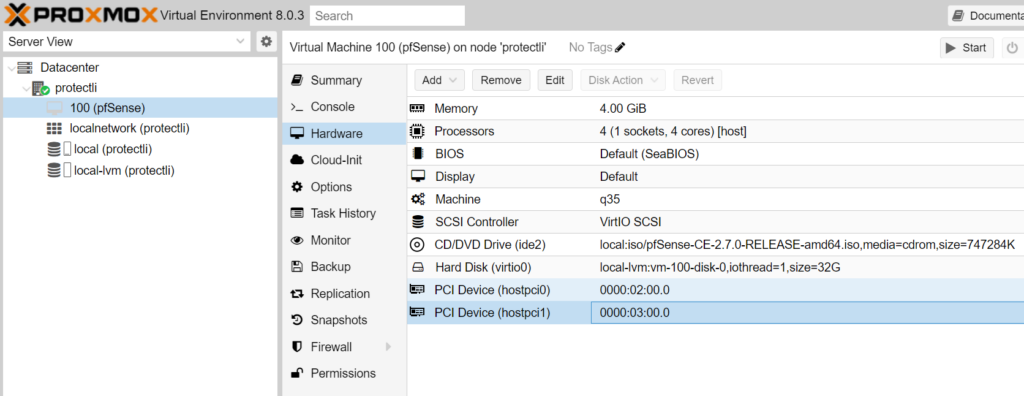
You should remove any existing Linux Bridges on the Hardware tab of the VM before proceeding.
In order to add your NICs to your VM to use as interface assignments, follow these steps:
- Go to the Hardware tab of your pfSense® CE VM
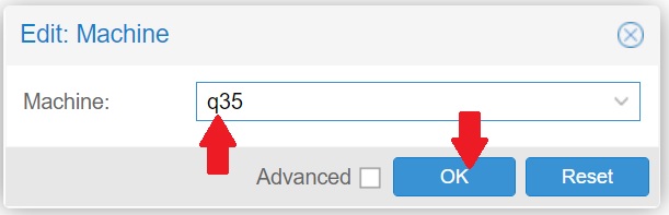
- Double click on Machine and choose q35, click Ok to confirm
- Go back to the Hardware tab, and Add a PCI Device
- Click on the Raw Device button
- From here, you can add whatever network connection you would like
- DO NOT passthrough the port you are already using for Proxmox VE's management (most likely port 1), this will cause issues when you boot the VM
- The screenshot below shows a list of all the ethernet ports on the VP2420, these will potentially be named differently depending on the device and NICs
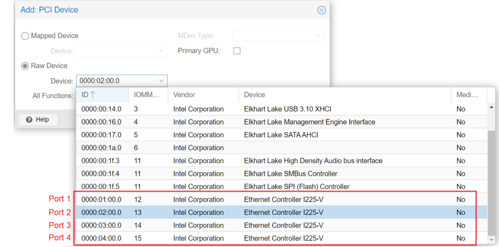
- For a WAN and LAN port, choose port 2 and 3 (see below screenshot)
Assigning the WAN and LAN Interfaces on pfSense® CE
- Load up the VM until asked to assign interfaces
- When asked to set up VLANs, type n and hit your Enter key
- for WAN: type igc0 (or potentially igb0) and hit Enter
- for LAN: type igc1 (or potentially igb1) and hit Enter
- *Note: these interfaces may be named differently depending on the NICs in your Vault (Ex: igb0, em0) Please pay attention to the console on what the proper names are for your NICs.
- When asked if you want to proceed: type y and hit Enter
You can now use these interfaces as normal. To access the Web GUI, go to the default address of 192.168.1.1 with a computer connected to your assigned LAN port.
Observed Throughput Speeds
The following chart displays the average observed throughput speeds on a pfSense® CE VM for each Vault. Tests were completed via iperf3 as well as the Speedtest® CLI.
The pfSense® CE VM was configured with 4GB of RAM, and installed with the same settings shown on this article.
For the iperf test: traffic was initiated on a host outside of the pfSense® CE VM. The traffic was routed through the pfSense® CE VM to a physical client connected to the LAN port of the Vault. We completed an additional test where the same iperf host routed traffic through the pfSense® CE VM, and into an Ubuntu 22.04 VM that was virtually connected to pfSense® CE via a Linux Bridge network interface.
We also tested throughput speeds while utilizing PCI Passthrough for the physical NICs.
For the Speedtest® CLI test: the same host server was used for each Vault.
| Vault | iperf: Physical Client on LAN Port | iperf: To Virtual Machine | Speedtest CLI: Physical Client on LAN Port | Speedtest CLI: To Virtual Machine | iperf: Physical Client on LAN Port (PCI Passthrough) | Speedtest CLI: Physical Client on LAN Port (PCI Passthrough) |
|---|---|---|---|---|---|---|
| FW2B | 326 Mb/s | 179 Mb/s | 189 Mb/s | 172 Mb/s | N/A | N/A |
| FW4B | 630 Mb/s | 560 Mb/s | 417 Mb/s | 373 Mb/s | N/A | N/A |
| FW4C | 801 Mb/s | 710 Mb/s | 520 Mb/s | 420 Mb/s | N/A | N/A |
| FW6A | 900 Mb/s | 780 Mb/s | 920 Mb/s | 625 Mb/s | 951 Mb/s | 942 Mb/s |
| FW6B | 949 Mb/s | 949 Mb/s | 953 Mb/s | 924 Mb/s | 952 Mb/s | 953 Mb/s |
| FW6C | 950 Mb/s | 950 Mb/s | 953 Mb/s | 936 Mb/s | 952 Mb/s | 955 Mb/s |
| FW6D | 952 Mb/s | 952 Mb/s | 958 Mb/s | 936 Mb/s | 952 Mb/s | 959 Mb/s |
| FW6E | 952 Mb/s | 952 Mb/s | 959 Mb/s | 936 Mb/s | 952 Mb/s | 960 Mb/s |
| VP2410 | 951 Mb/s | 949 Mb/s | 939 Mb/s | 914 Mb/s | 952 Mb/s | 942 Mb/s |
| VP2420 | 2350Mb/s | TBD | TBD | TBD | 2370Mb/s | TBD |
| VP4630 | 2370Mb/s | TBD | TBD | TBD | 2370Mb/s | TBD |
| VP4650 | 2370 Mb/s | TBD | TBD | TBD | 2370 Mb/s | TBD |
| VP4670 | 2370Mb/s | TBD | TBD | TBD | 2370Mb/s | TBD |